IP v6 Connecting Tomorrow's Internet Today

An Internet Protocol Version 6 address (IPv6 address) is a numerical label that is used to identify a network interface of a computer or other network

This is default featured slide 2 title

Go to Blogger edit html and find these sentences.Now replace these sentences with your own descriptions.This theme is Bloggerized by Lasantha Bandara - Premiumbloggertemplates.com.

Team Work...

"a joint action by a group of people, in which each person subordinates his or her individual interests and opinions to the unity and efficiency of the group."

This is default featured slide 4 title

Go to Blogger edit html and find these sentences.Now replace these sentences with your own descriptions.This theme is Bloggerized by Lasantha Bandara - Premiumbloggertemplates.com.

System fail situation in network server room

A system failure can occur because of a hardware failure or a severe software issue. Commonly, a system failure will cause the system to freeze, reboot, or stop functioning altogether.

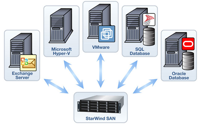
Optimizing Servers, Data and Storagewith End-User Provision

A new server and storage system can keep your businesses current with technology and best practices, reduces cost, provide quickly Return On Investment on your business and help end users become more productive and collaborate

How To Activate Exchange Server 2010

1) Open Exchange Server Management Console

Click on Start > All Programs > Microsoft Exchange Server 2010 > Microsoft Exchange Management Console


  • Once the Management Console is opened, it will display for you the unlicensed exchange servers and the remaining days for the trial period.


  • In the console tree, navigate to Server Configuration


  • From the right side pane, in the Actions pane, click on Enter Product Key...


  • On the Enter Product Key page, enter the product key, then click Enter


  • On the Completion page, a status message will be displayed showing you if either the wizard completed successfully or it failed. If it failed, then click Back to make any configuration changes.


    After you have a successful Exchange Server activation, you can see that the Enter Product Key... option is not available anymore under the Actions pane.


    Note : You must restart the Microsoft Exchange Information Store service so that the change is applied.
  • ...................................................................()()()()()()..................................................................
     
    2)
    Your Exchange server will run for 120 days without a product key but you should enter one as soon as possible and certainly before placing the server into production.
    Launch the Exchange Management Console from the Start Menu of the server.  A warning will appear listing each Exchange server that is currently unlicensed.  Click OK to clear the warning.
    In the left pane of the Exchange Management Console navigate to Server Configuration.  Right-click the server in the middle pane and choose Enter Product key.

    Enter your Product Key in the field and then click the Enter button.

    You will see a message when the Product Key has been applied warning you that the change does not take effect until the Information Store service is restarted.  Close the warning dialog box.


    Installing DHCP and Windows Deployment Services

    DHCP Introduction

    When you deploy Dynamic Host Configuration Protocol (DHCP) servers on your network, you can automatically provide client computers and other TCP/IP-based network devices with valid IP addresses. You can also provide the additional configuration parameters these clients and devices need, called DHCP options, that allow them to connect to other network resources, such as DNS servers, WINS servers, and routers.

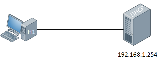
     IP addresses can be configured statically or dynamically. Normally we configure static IP addresses on network devices like routers, switches, firewalls and servers while we dynamically assign IP addresses to computers, laptops, tablets, smartphones etc. The dynamic method uses DHCP (Dynamic Host Configuration Protocol) and in this short article I want to show you how it works. Let’s take a look at the following picture:

    DHCP Topology

    On the left side we have a computer without IP address. On the right side there’s a DHCP server configured with static IP address 192.168.1.254. This DHCP server will supply an IP address to our computer, this is how it works:

    DHCP Discover

    The computer will send a DHCP discover message. This is a broadcast because it doesn’t have an IP address and it doesn’t know if there is a DHCP server on the network. Of course in our scenario we do have a DHCP server so it will respond to this broadcast as following:

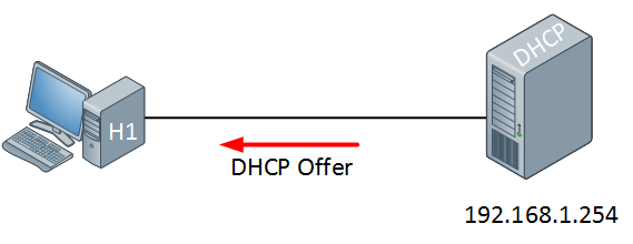
    DHCP Offer

    The DHCP server will respond with a DHCP offer message which contains an IP address for the computer (we have to configure the DHCP server to define which IP addresses we want to give). If we want we can also assign a default gateway and DNS server(s) to the computer. The computer will respond to this information:

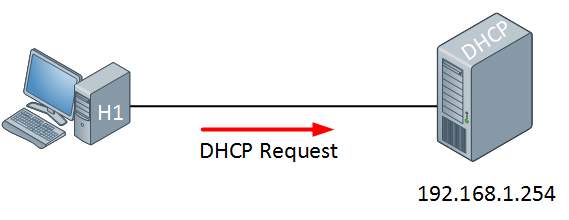
    DHCP Request

    The computer will send a DHCP Request in response to the DHCP offer message, asking nicely if it’s OK to use the information that it has received. Our DHCP server will respond to this as following:

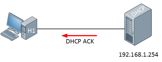
    DHCP ACK

    The DHCP server will respond with a DHCP ACK message to tell the computer it’s OK


    • Before installing WDS we have to create a new partition to hold our image files
      1. Open Server Manager
      2. Click Storage
      3. Click Disk Management
      4. Right click Unallocated
      5. Click Create New Volume
      6. Click Next
      7. Click Next
      8. Change drive letter to I
      9. File: NTFS
      10. Allocation: default
      11. Click Next
      12. Volume label: Images
      13. Check Perform Quick Format
      14. Click Next
      15. Click Finish
    pic1
    • Open Server Manager
      1. Click Roles in menu at top left
      2. Click Add Roles at right
    pic2
    • Check Skip this page by default
    • Click Next
    pic1
    • Select Server Roles
      1. Check DHCP
      2. Check Windows Deployment Services
      3. Click Next
    pic2
    • Overview of Windows Deployment Services
      1. Click Next
    pic3
    • Select Roles Services
      1. Click Next
    pic4
    • Check box next to 192.168.9.1
    • Click Next
    pic8
    • Specify IPv4 DNS Server Settings
      1. Parent Domain: Adatum9.com
      2. Preferred DNS Server IPv4 Address: 192.168.9.1
      3. Alternate DNS Server IPv4 Address: 192.168.9.2 (Virtual Server)
      4. Click Next
    pic6
    • Specify IPv4 WINS Server Settings
      1. Check radio button next to: WINS is not required for applications on this network
      2. Click Next
    pic7
    • Add or Edit DHCP Scopes
      1. Click Add
    pic8
    • Add Scope
      1. Scope Name: scope9
      2. Starting IP Address: 192.168.9.1
      3. Ending Ip Address: 192.168.9.10
      4. Subnet Mask: 255.255.255.0
      5. Default Gateway (optional): 192.168.9.1
      6. Subnet Type: Wired (lease duration will be 6 days)
      7. Click OK
    • Click Next
    pic9
    • Configure DHCPv6 Stateless Mode
      1. Check Disable DHCPv6 stateless mode for this server.
      2. Click Next
    pic10
    • Authorize DHCP Server
      1. Check Use current credentials
      2. Click Next
    pic11
    • Confirm Installation Selections
      1. Click Install
    pic12
    • Installation Results
      1. Click Close
    • Go to Start\Administrative Tools\DHCP
    • Click Properties
    • Click + beside of DHCP
    • Click + beside of IPv4
    • Right click Scope and choose Properties
    pic13
    • Click Advanced tab
    • Check Both
    • Click OK
    • How to exclude a range of ip addresses from the DHCP pool.
    • Right click the address pool
    • Click New Exclusion Range
    pic14
    • 192.168.9.1
    • 192.168.9.2
    • Click Add
    • Click Close
    • Close DHCP Window

    Sharing Your Computer with Others Create a Homegroup

    Sharing Your Computer with Others : Create a Homegroup


    8/4/2013 9:41:41 AM

    You can share documents and media easily with other Windows 7 computers by creating a homegroup on your network. A homegroup simplifies network sharing by making it easy to create a homegroup and share documents, pictures, music, videos, and even printers.
    You use one Windows 7 computer to create the homegroup, and Windows 7 assigns a password for that homegroup. You then use the password to join your other Windows 7 computers to the homegroup. 
    Create a Homegroup
    1 Click Start.
    2 Click Documents.
    The Documents library appears.
    3 Click Homegroup.
    4 Click Create a homegroup.


    The Create a Homegroup Wizard appears.


    5 Click the check box for each type of file you want to share with the homegroup ( changes to ).
    6 Click Next(not shown).
    Windows 7 creates the homegroup.
    • The Create a Homegroup Wizard displays the homegroup password.
    7 Write down the homegroup password.
    • Alternatively, you can click this link to print the password.
    8 Click Finish.
    You can now join your other Windows 7 computers to the homegroup, as described in the next section.

    Simplify It

    I have lost my homegroup password. How do I view it again?
    Click Start, and then click Control Panel to open the Control Panel window. Under the Network and Internet heading, click Choose homegroup and sharing options to open the Homegroup window. Click the View or print homegroup password link to see your password. To print the password, click Print this page.
    Is it possible to change the homegroup password?
    Yes. Click Start, and then click Control Panel to open the Control Panel window. Under the Network and Internet heading, click Choose homegroup and sharing options to open the Homegroup window. Click the Change the password link and then click Change the password to generate a new homegroup password. If one or more computers have already joined the homegroup, you need to provide them with the new password.

    How to configure ftp server in windows

     FTP Server using IIS 7.0 and Windows Server 2008

    • Open Server Manager, go to Roles and click “Add Roles”
    1.png
    • In the Add Role Wizard, select Web Server (IIS) role to install
    2.png
    • Click Next until you reach Select Role Services page, leave the default and check FTP Server, FTP Service and FTP Extensibility at the bottom. Click Next, follow the wizard and finish the role installation.
    3.png
    • Now open IIS Manager from Start > Administrative Tools, expand the server, right click Sites, and click Add FTP Site, give it a site name and configure the physical path as needed.
    4.png
    • Configure Binding and SSL. In our case, we’d like to bind to all unassigned IP addresses and do not use SSL.
    5.png
    • Enable Basic Authentication and configure authorization. In our case I’ll start with allowing All users both Read and Write permission as long as all users on the server are password protected.
    6.png
    • Click Finish to finish the configuration.

    • Open Windows Firewall with Advanced Security from Start > Administrative Tools, go to Inbound Rules in the left pane, and create a new rule by clicking New Rule in the Action Pane, select Port and click next.
    7.png
    • Apply this rule to TCP port 21, and click Next
    8.png
    • Keep the default configure for the rest of steps to Allow the connection and apply it to all profiles, name the rule and finish the wizard.

    • Now the FTP should be up and running, please test the connection to confirm.
     =======================================================================

    Networking questions answers, Ethernet - Q&A

    Questions

    1. What is Ethernet?
    2. To which OSI layer does Ethernet belong?
    3. What are the standard data rates for Ethernet?
    4. What are the different IEEE standards that cover Ethernet?
    5. How two systems in an Ethernet network communicate?
    6. What is a "collision"?
    7. How is "collision" handled in Ethernet networks?
    8. What is CSMA/CD?
    9. What is "late collision"?
    10. How "late collision" is avoided in Ethernet networks?
    11. What is an Ethernet address?
    12. What is a broadcast address?
    13. What are the different Ethernet frame formats?
    14. Why there are different Ethernet frame formats?
    15. What is the format of an Ethernet II frame?
    16. What is the format of an 802.3 frame?
    17. What is the format 802.2 SNAP frame?
    18. How is the length of an Ethernet II frame calculated?
    19. What is the minimum and maximum size of an Ethernet frame?
    20. What is a SAP?
    21. Why SNAP header is required?
    22. What are the values for SSAP, DSAP, control and org fields in a 2.2 SNAP frame?
    23. How to differentiate between an 802.3 frame and an Ethernet II frame?
    24. What is promiscuous mode?
    25. What is MTU?

    Answers

    1. What is Ethernet?
      Ethernet is a Local Area Network (LAN) cabling and signaling specification for baseband networks. Ethernet uses a bus or star topology for connecting different nodes in a network.
    2. To which OSI layer does Ethernet belong?
      Ethernet belongs to both the Physical Layer (Layer 1) and the Data Link layer (Layer 2) in the OSI architecture.
    3. What are the standard data rates for Ethernet?
      The standard data rates for Ethernet are 10 Mbps, 100 Mbps, and 1 Gbps
    4. What are the IEEE standards that cover Ethernet?
      The following IEEE standards define Ethernet:
         +--------+----------------------------------------------------+
         |IEEE    |                  Description                       |
         |Standard|                                                    |
         +--------+----------------------------------------------------+
         |802.2   |Logical Link Control (LLC) Specification.  Specifies|
         |        |the general interface between the network layer     |
         |        |(IP, IPX, etc) and the data link layer (Ethernet,   |
         |        |Token Ring, etc).                                   |
         +--------+----------------------------------------------------+
         |802.3   |CSMA/CD Network (Ethernet) Specification.  Specifies|
         |        |the frame format, cabling and signaling standards.  |
         +--------+----------------------------------------------------+
      
    5. How two systems in an Ethernet network communicate?
      In a Ethernet network, a system broadcasts the data using a Ethernet frame. The destination system is specified in the Ethernet frame using its Ethernet address. All the systems in the network listen for an Ethernet frame with their Ethernet address in it. When a system receives an Ethernet frame with its address in it, it processes the frame and sends it to the higher layers (like IP) for further processing.
    6. What is a "collision"?
      At any one instance, in an Ethernet network, only one device can transmit. If two devices transmit at the same instance, then the signals from both devices will collide and a "collision" will occur. When a "collision" occurs, the signals will get distorted and the frame will be lost. Collisions are very common in a Ethernet network.
    7. How is "collision" handled in Ethernet networks?
      Ethernet uses the Carrier Sense Multiple Access with Collision Detection (CSMA/CD) media access control mechanism to detect and recover from a collision.
    8. What is CSMA/CD?
      CSMA/CD is a media access control mechanism used in Ethernet to recover from frame collision. The following steps are followed to recover from a collision.

        Step 1: Before an Ethernet device sends a frame on the Ethernet cable, it listens to find if another device is already transmitting a frame (Carrier Sense).
        Step 2: Once the device finds that other devices are not transmitting any frame, it starts transmitting the frame. If two devices detect that the Ethernet cable is free at the same time, then both will start transmitting the frames (Multiple Access). This will result in collision.
        Step 3: The Ethernet devices while transmitting the frames, also listen for the collision. (Collision Detect).
        Step 4: If they detect a collision, both the devices stop sending the frame (back off).
        Step 5: They retry the transmission after a logarithmic time-out period. This process is repeated till the frame is transmitted successfully, for a maximum of 16 times. The frame is discarded after the 16th retry.
    9. What is "late collision"?
      An Ethernet device will detect a collision, while it is transmitting, only if the collision reaches it before it completes transmitting the entire frame. If the collision reaches the transmitter, after it completed sending the entire frame, then the transmitter will not detect the collision, it will assume the collision occurred because of some other frame. This is called "late collision". Late collision will occur, if the length of the Ethernet network segment is greater than the standard allowed length.
    10. How "late collision" is avoided in Ethernet?
      Late collision can be avoided, if the maximum length of the Ethernet network segment is restricted, such that if a collision occurs, it will reach the transmitter before the transmitter completed transmitting the entire frame. In a typical 10 Mbps network, the minimum length of an Ethernet frame is 576 bits (72 bytes) and the maximum length of a single Ethernet network segment is 2.5 kms.
    11. What is an Ethernet address?
      Each device in an Ethernet network is uniquely identified by a 48 bit (6 bytes) address called Ethernet address. Ethernet address is also known as Media Access Control (MAC) address. Ethernet addresses are represented as six pairs of hexadecimal digits separated by a colon. Ethernet address are buried in the network adapter by the manufacturer. A Ethernet address of a device cannot be changed. Example: 00:60:08:11:B1:AB, 00:00:c0:5e:83:0e
    12. What is a broadcast address?
      The Ethernet address in which all the bits are 1 is known as a broadcast address. It is represented as FF:FF:FF:FF:FF:FF. A frame with this address is received and processed by all the nodes in the network.
    13. What are the different Ethernet frame formats?
      The different Ethernet frame formats are listed below: Ethernet II and IEEE 802.3
    14. Why there are different Ethernet frame formats?
      Xerox developed the first version of Ethernet, Ethernet I. The second version of Ethernet, Ethernet II, was developed by DEC, Intel and Xerox. After this the Ethernet was standardized by IEEE and the new format is known as 802.3 format. To provide backward compatibility with Ethernet II, 802.2 SNAP format was developed.
    15. What is the format of an Ethernet II frame?
          +-----------+----------+----------+-----------+----------+
          |Destination|Source MAC|Frame type|Data       | CRC      |
          |MAC Address|Address   |(IP, ARP) |(46 to     | Checksum |
          |(6 bytes)  |(6 bytes) |(2 bytes) |1500 bytes)| (4 bytes)|
          +-----------+----------+----------+-----------+----------+
      
    16. What is the format of an 802.3 frame?
      The various components of an 802.3 frame are shown below:
          +----------+---------+-----------+----------+
          |802.3 MAC |802.2 LLC|Data       | CRC      |
          |Header    |Header   |(43 to     | Checksum |
          |(14 bytes)|(3 bytes)|1497 bytes)| (4 bytes)|
          +----------+---------+-----------+----------+
      
      The first two components, MAC Header and LLC Header are further expanded below: 802.3 MAC Header:
          +-----------+----------+---------+
          |Destination|Source MAC|Length of|
          |MAC Address|Address   |the frame|
          |(6 bytes)  |(6 bytes) |(2 bytes)|
          +-----------+----------+---------+
      
      802.2 LLC Header:
          +-----------+--------+--------+
          |Destination|Source  |Control |
          |SAP        |SAP     |Byte    |
          |(1 byte)   |(1 byte)|(1 byte)|
          +-----------+--------+--------+
      
    17. What is the format of an 802.2 SNAP frame?
          +----------+---------+----------+-----------+----------+
          |802.3 MAC |802.2 LLC|802.2 SNAP|Data       | CRC      |
          |Header    |Header   |Header    |(38 to     | Checksum |
          |(14 bytes)|(3 bytes)|(5 bytes) |1492 bytes)| (4 bytes)|
          +----------+---------+----------+-----------+----------+
      
      The 802.2 SNAP header is further expanded below. 802.2 SNAP Header:
          +---------------------+---------+
          |OUI (Organizationally|Type     |
          |Unique Id)           |(2 bytes)|
          |(3 bytes)            |         |
          +---------------------+---------+
      
    18. How is the length of an Ethernet II frame calculated?
      The length of an Ethernet II frame is not present in the frame itself. It depends on the Ethernet network interface used. When the interface sends a frame to the network device driver, it supplies the length of the received frame.
    19. What is the minimum and maximum size of an Ethernet frame?
      The minimum size of an Ethernet frame is 64 bytes. The breakup of this size between the fields is: Destination Address (6 bytes) + Source Address (6 bytes) + Frame Type (2 bytes) + Data (46 bytes) + CRC Checksum (4 bytes). The minimum number of bytes passed as data in a frame must be 46 bytes. If the size of the data to be passed is less than this, then padding bytes are added. The maximum size of an Ethernet frame is 1518 bytes. The breakup of this size between the fields is: Destination Address (6 bytes) + Source Address (6 bytes) + Frame Type (2 bytes) + Data (1500 bytes) + CRC Checksum (4 bytes). The maximum number of bytes of data that can be passed in a single frame is 1500 bytes.
    20. What is a SAP?
      SAP, Service Access Point, is the logical point at which services are provided by an OSI layer. Typically, the protocols in the network layer (like IP) bind at specific SAP in the Logical Link Control Layer( LLC) for accessing the services provided by it.
    21. Why Sub Network Access Protocol (SNAP) header is required?
      The 802.2 LLC header replaces the 'protocol type' of the Ethernet II format with two SAP fields, Source SAP and Destination SAP. The value of the SAP field in the 802.2 header is equivalent to the 'protocol type' field in the Ethernet II header. The value of the SAP field will be between 1 and 255, since it is an 8 bit field. On the other hand, the 'protocol type' value for the standard protocols like IP, ARP, etc is grater than 1500. Obviosuly, these values cannot be represented in the SAP fields. So to provide compatibility with Ethernet II, SNAP header was added to the 802.2 LLC header. In a SNAP frame, both the SAP values will be 0xAA and the first 5 bytes of the data will give the protocol ID. Out of the 5 bytes of data, the last 2 bytes are same as the protocol type field of the Ethernet II frame. The first 3 bytes are called as 'Organizationally Unique Identifer' (OUI) and are allocated as a vendor identifier. Typically, OUI will be zero.
    22. What are the values for SSAP, DSAP, control and org fields in a 802.2 SNAP frame?
          +-------+-----+
          |Field  |Value|
          +-------+-----+
          |SSAP   |0xAA |
          |DSAP   |0xAA |
          |Control|3    |
          |OUI    |0    |
          +-------+-----+
      
    23. How to differentiate between an 802.3 frame and an Ethernet II frame?
      The value of 'length' field in an 802.3 frame must be less than 1500 and in a Ethernet II frame the value of 'type' field must be more than 1500. Since the 802.3 frame 'length' field and the Ethernet II frame 'type' field are at the same offset from the header, depending on the value present, the frame can be differentiated.
    24. What is promiscuous mode?
      Normally, a Ethernet network interface will pass a frame to the above network layers only if it is addressed to that interface. If the network interface is put in the promiscuous mode, the Ethernet network interface will send all the frames (frames addressed to any host in the network), regardless of their destination address to the above network layers. This mode is used by network analyzers to capture all the frames.
    25. What is MTU?
      Maximum Transmission Unit (MTU) is the maximum number of bytes that can be transmitted in a single transmission unit. Every communication medium has a MTU. For Ethernet, the MTU of a frame is 1500.


    Connect Visual Studio 2010 to Your TFS Preview Account

    1
    Download the software.
      You need to ensure that you are running Visual Studio 2010 SP1 on your (local) computer
    and that you install KB2581206.
    2
    Open Visual Studio 2010. In Team, select Connect to Team Foundation Server…
      image
    3
    Click Servers…
      image
    4
    Click Add…
      image
    5
    Type your TFS Preview account URL
    This is the same URL you use to access your account online.
      image
    6
    Click OK to add the server.
    Click Close to return to the Connect screen.
    Select your team project and click Connect.
      image